








News & Insights
Stay Informed. Stay Connected.

Send Us A Message
Sodium Bicarbonate in Flue Gas Treatment: Key Operating Factors
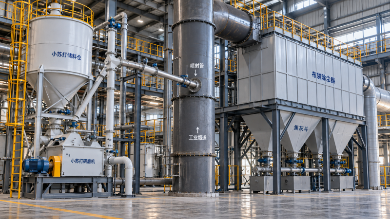
Sodium bicarbonate can provide effective acid-gas control in a dry sorbent injection system, but reagent selection alone does not determine the result. The same material may perform differently when gas temperature, particle size, injection location or filter operation changes. A system that meets an emissions target during a steady trial can also struggle when pollutant concentrations rise or gas flow shifts.
The practical design question is not simply how much reagent to inject. It is how to deliver sufficiently reactive material into the right part of the duct, keep it in contact with the gas, capture the resulting solids and maintain that performance across the plant’s operating range. Those requirements also determine reagent consumption, equipment capacity and waste handling costs.
Start with the gas stream and the emissions objective
Sodium bicarbonate is used to neutralize acidic flue-gas components, particularly hydrogen chloride (HCl), sulfur dioxide (SO2) and hydrogen fluoride (HF). It is relevant to applications such as waste-to-energy facilities, industrial boilers and other combustion processes where acid gases must be controlled. The required system configuration depends on which pollutants are present, their concentrations and the emissions limits that apply to the installation.
A representative gas profile matters more than a single average reading. Fuel composition, feedstock changes, startup conditions and process upsets can all alter the acid load. If the injection system is sized only for average conditions, it may lack the capacity to respond to short peaks. Conversely, designing every component around a rare maximum without considering its duration can add unnecessary capital and operating cost.
Gas flow is equally important. A given pollutant concentration represents a larger mass load when more gas passes through the duct. The design basis should therefore connect pollutant concentration with flow, temperature and operating duration for each relevant condition. It should also state whether the system must work on its own or alongside existing treatment equipment.
Dry injection is often attractive for a retrofit where an existing duct and suitable particulate collector are available and adding a wet system would be difficult. It is less straightforward where there is insufficient space for mixing and solids separation, where the existing collector has little spare capacity, or where disposal of sodium-containing residues is constrained. In those cases, reagent performance cannot be separated from the limitations of the whole plant.
Temperature affects activation and equipment selection
When heated, sodium bicarbonate decomposes to form sodium carbonate, releasing carbon dioxide and water. This thermal transformation creates a more reactive sorbent structure that can neutralize acid gases. Gas temperature therefore affects how readily the injected material becomes available for reaction.
At a cooler injection point, activation may be slower or incomplete, leaving less effective material before the gas reaches the collector. At a hotter point, activation can be more favorable, but other limits may govern the choice: duct materials, conveying equipment, injection hardware, downstream filter media and available maintenance access. The preferred location is the one that works for the entire operating envelope, not just the highest-temperature condition.
Temperature should be assessed together with residence time. A location with suitable gas temperature may still provide too little time for dispersion, activation and reaction before the gas reaches a bend or collector inlet. Conversely, moving the injection point farther upstream may create additional contact time but expose the system to different gas conditions or increase the risk of solids accumulating in the duct.
Moisture also deserves attention. Flue-gas moisture can influence reaction behavior, while condensation or water ingress can cause handling and deposit problems. Keep stored reagent dry, and review startup and shutdown conditions when duct temperatures may pass through condensation-prone ranges.
Particle size is a system decision, not just a product specification
Finer sodium bicarbonate generally offers more surface area for reaction, which can improve sorbent utilization. Coarser particles may be less completely used during the available contact time, particularly when duct residence time is short. A finer powder, however, can introduce its own challenges in storage, feeding and conveying, and milling adds equipment and energy demand.
Many installations use a mill to prepare the sorbent before injection. When evaluating this arrangement, consider the complete path from bulk storage to the injection lances: the incoming material’s particle-size distribution and flow behavior, mill capacity, conveying air, feeder stability and access for cleaning. A mill sized for nominal reagent demand should also be able to support the injection rate needed during high acid-gas loads.
Particle size should be specified as a distribution, not only as a single average. A material with too many coarse particles may reduce utilization, while excessive fines can make dust containment and handling more demanding. The useful target is the size distribution that achieves the required emissions performance consistently with the installed mill, duct and collector.
When sourcing sodium bicarbonate, ask for the characteristics relevant to the intended handling and milling arrangement, including composition, moisture, particle-size distribution and any limits on insoluble material. Shandong Junzheng Chemical Co., Ltd. lists sodium bicarbonate among its chemical products; the suitability of a particular supply still depends on how its specifications match the proposed system.
Injection rate and mixing determine how much reagent is actually used
The theoretical amount of sorbent needed follows from the acid-gas load and the neutralization reactions. In operation, some excess is usually needed because mixing is imperfect, reactions take time and not every particle is fully utilized. The appropriate operating rate is therefore established against the required outlet emissions under representative conditions, rather than fixed solely from a chemical calculation.
More reagent does not always solve a performance problem efficiently. If the powder enters only one side of the duct, a portion of the gas can pass through with insufficient contact while excess material travels elsewhere. Poor distribution, unsuitable lance orientation, inadequate conveying air or deposits around the injection point can all increase consumption without delivering the expected improvement.
Review the duct layout before fixing the injection location. Bends, transitions and nearby equipment affect the gas velocity profile and the way particles disperse. Injection lances must also remain accessible for inspection and cleaning. A layout that looks adequate on a drawing may perform poorly if it leaves most of the sorbent concentrated in a narrow stream.
Control strategy matters when emissions vary. A fixed feed rate is simple but may overfeed during low-load operation and underfeed during peaks. A system linked to plant load or measured acid-gas conditions can respond more closely to demand, provided the instruments are reliable and the feeder has sufficient response range. Analyzer lag, transport delay and feeder response should be considered together; an aggressive control loop can otherwise chase old measurements and cause unstable dosing.
The particulate collector is part of the treatment process
After injection, the gas carries unreacted sorbent and reaction products downstream. These solids must be captured. In a fabric filter, material collected on the bags forms a dust layer that can provide additional gas-solid contact. Filter performance therefore affects both particulate emissions and the overall use of the reagent.
Adding dry sorbent increases the solids load on the collector. Before selecting an injection rate, assess whether the filter, cleaning system, hoppers and conveying equipment can handle the additional material across normal and peak operation. Monitor pressure drop and cleaning behavior: a rising pressure drop may indicate a growing or difficult-to-clean dust layer, while an unusual decrease can signal leakage or another change requiring investigation.
Existing ash characteristics also matter. The mixture of process dust, unreacted reagent and sodium salts may behave differently from the solids the collector previously handled. Hopper discharge, storage capacity and downstream transport should be evaluated for the combined residue, not only for the original ash stream.
Electrostatic precipitators and other collectors can also be used in dry injection arrangements, but their operating behavior differs from a fabric filter. Do not assume that results from one collector type will transfer directly to another: available reaction time, solids capture and equipment constraints all affect performance.
Plan for residue handling before commissioning
Neutralization changes the quantity and composition of collected solids. The residue can contain sodium salts, unreacted sorbent and constituents already present in the process dust. Its handling route depends on the actual composition and applicable local requirements, not just on the reagent’s starting specification.
Include residue sampling, storage and disposal or recovery options in the project scope. If the plant has an established ash reuse route, determine whether the added sodium and soluble salts are compatible with that outlet. A treatment system that meets stack limits can still create an operating problem if the resulting solids cannot be moved or managed reliably.
Dry powder handling also requires attention to dust containment and worker exposure. Enclosed transfer points, suitable dust collection, safe access for maintenance and procedures for clearing blockages should be considered alongside the process design. Storage arrangements should protect the material from moisture and support a consistent feed to the system.
Commission against changing conditions, not one favorable test
A useful commissioning program establishes how reagent consumption and outlet emissions respond to changes in gas load, temperature and injection rate. It also identifies whether performance is limited by chemistry, distribution, instrumentation or the collector. Before adjusting the feed, confirm that the feeder delivers the intended quantity, the mill produces the required material and the injection points are clear.
During controlled trials, record inlet and outlet acid-gas measurements where available, gas flow and temperature, reagent rate, collector pressure drop and relevant plant operating conditions. Compare periods with similar process conditions before attributing a change in emissions to the sorbent rate. A change in fuel or feedstock can otherwise be mistaken for an improvement or deterioration in injection performance.
Use the results to establish operating settings for normal loads and a response plan for higher acid loads. The plan should define how operators recognize insufficient treatment, what checks precede a dose increase and when to inspect the mill, lances or collector. It should also account for analyzer availability: loss of an instrument signal requires a defined control response, not an assumption that the last reading remains valid.
For a new installation or retrofit, the next step is to assemble the gas-load profile, available duct and collector information, reagent handling requirements and residue route into one design basis. That gives equipment suppliers a consistent set of conditions to work from and makes it easier to compare proposals on sustained emissions control, total reagent use and practical operability.
Send Us Your Inquiry Today